PURPOSE OF SCALINGS
The scaling is the set of parameters used to derive the engineering value from the binary value read from the device.
They apply to channels and descriptor variables.
The parameters are 4 and are defined as follows:
-
Gain 1
-
Offset 1
-
Gain 2
-
Offset 2
to be applied in the formula ((binary-value * gain1) + offset1) / ((binary-value *gain2) + offset2)
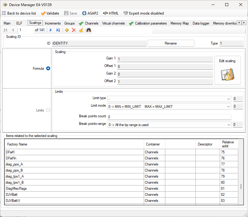
COMMAND BAR
Navigation commands
These commands allow you to move through the records in the database table that contains the scalings.
Add command
Used to add a new entry to the list of scalings.
This opens the page for adding / editing a scaling.
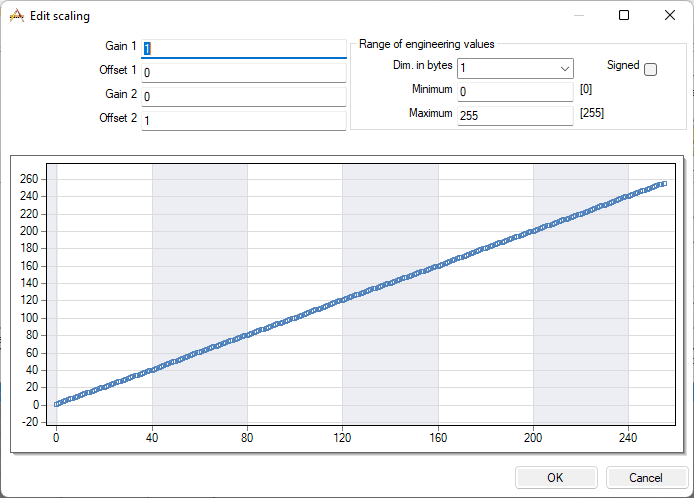
Enter the scaling parameters and confirm with OK. It will be proposed a name to identify the scaling. The name can be changed but it must not be equal to another name already used. If the name you typed is the same as an existing name, ECT alerts you with a message.
You can check how the scaling works by setting in the ‘range of the engineering values’ the attributes of a hypothetical variable that will be associated with this type of scaling. To do this you need to specify:
-
the byte count of the variable
-
the boolean attribute ‘Signed’. As a result you will have the minimum and maximum value that the variable can take and the graph that relates the binary value on the x axis and the engineering value on the y axis.
Delete command
Used to delete an entry from the list of scalings.
The command is rejected if the scaling is used in the database as attribute of a channel or calibration variable.
Delete unused items
This command checks if there are unused scalings and deletes them.
Search command
In the text area next to the binoculars, you can specify the ID of a scaling to be searched.
The research starts when you press the Enter key. A further press of the Enter key allows you to search for the next occurrence. At the last event, by pressing again the Enter key, you return to the first occurrence.
The command supports wildcards
SCALING ID AREA
This area contains the unique scaling ID display box and the ID rename command. The rename command is accepted only if the new name does not already exist.
FORMULA AREA
This area contains the display boxes for scaling parameters and the command to change the parameters. See details about the scaling parameters insert / edit page in the ‘Add command’ section.
RELATED ITEMS AREA
This area contains the list of channels and calibration variables that use the selected scaling.
The calibration variables belonging to different descriptors from the selected one are highlighted in gray.
If this list is empty you can use the command ‘Delete’.