• Home
  • Privacy policy
  • Italiano
  • English
  • Home
  • Privacy policy
  • Italiano
  • English
  • Software
    • ECT
      • ACKNOWLEDGEMENT
      • SYSTEM REQUIREMENTS
      • COMMUNICATION SCHEMES
      • DIRECTORY STRUCTURE
      • AVAILABLE TOOLS
      • INSTALLATION
      • GETTING STARTED
      • MAIN MENU
      • DEVICE EDITOR
        • ELF ORIENTED DEVICES AND NOT ELF ORIENTED DEVICES
        • STORAGE STRUCTURE OF THE DEVICE DATABASES
        • DEVICE LIST
          • CONTEXTUAL MENU IN THE DEVICE LIST
          • TOP BAR MENU
        • PAGE FOR EDITING THE VALUES IN THE DATABASE
          • TOP BAR MENU
          • MAIN - COMMUNICATION PARAMETERS AND OTHER SETTINGS
          • SCALINGS SECTION
          • INCREMENT SECTION
          • GROUPS SECTION
          • CHANNELS
          • CALIBRATION PARAMETERS
          • MEMORY MAP
        • COMMAND LINE USAGE
      • MEMORY INTERFACE
        • SEND (PC->ECU)
        • LEARN
        • RESET DIAGNOSTIC DATA
        • HDP/CRP MANAGER
        • MEMORYINTERFACE SETTINGS
      • DISPLAY
        • TYPES OF CONTAINERS
        • PROFILE STRUCTURE
        • CONTAINER MANAGEMENT
        • CONTROLS
        • MODIFICATION OF A CONTAINER
        • DATA RECORDING - F3 LOG
        • DISPLAY SETTINGS
      • CALIBRATION EDITOR
        • CALIBRATION TYPES
        • LOADING A CALIBRATION
        • WORKING WITH CALIBRATION EDITOR
        • CALIBRATION COMPARISON
        • PRINT THE VALUES OF THE CALIBRATION VARIABLES
        • SAVING CHANGES
        • DELETING A CALIBRATION FILE
        • CALIBRATION SETTINGS
      • ASAP3
      • CHARTING TOOL
        • LOADING A DATA FILE
        • MAIN MENU
        • CHANNEL LIST
        • CURSOR
        • SEGMENTS
        • DISPLAY LAYOUT
        • DISPLAY ORIENTATION
        • ZOOM
        • LINK ANALYSIS DISPLAY WITH ENGINE MAP
      • APPENDICES
        • STRING FORMAT
      • VERSION HISTORY

DISPLAY LAYOUT

75 views 0


You can create personalised data layouts, making it easy to switch between for example analysis of combustion, gear shift and traction control.

Opening the tool select the channels you want to open for a specific layout.

If you loaded all channels when you opened the tool, you can generate a personalised layout by de-selecting channels.

  • Select channels to be included in the new group by un-ticking the box Visible to remove data channels you do not want to display in your personalised group.
  • Select your preferred colour for the data channel.
  • Tick the box Axis to add the channel scale on the left Y-axis in the display segment.
  • Select in which segment of 5 to display the data channel.
  • Select the line width; recommended setting is 1.

When the display is created, click the icon

to save the layout.

Click the icon

to load a layout. Select your layout CTTX file.


Once a new layout has been created, any changes made to it will be saved automatically when the layout is closed.

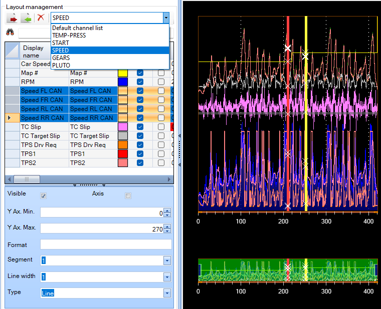
You can load several layouts in a display screen. All the loaded layouts will be listed in the combobox in the ‘layout management’ panel.

Switch between layouts by selecting an items of the combobox

MINIMUM AND MAXIMUM VISIBLE Y

The tool will automatically set minimum and maximum channel values but you can change these to suit your preferences.

To change the minimum and maximum y use the  ‘Y ax. min.‘ field or ‘Y ax. max.‘ field in the channel table or the fields in the table below if you want to change the minimum or maximum y simultaneously for all selected channels.

When some channels are selected, the cells of the selected channels table turn blue and their attributes can be changed in the table below.

HOW TO MAXIMIZE THE GRAPHIC DISPLAY WINDOW

You can maximise the graphic display window by closing the channel list.

Click on the bar « marked in red, to expand the graphic window.
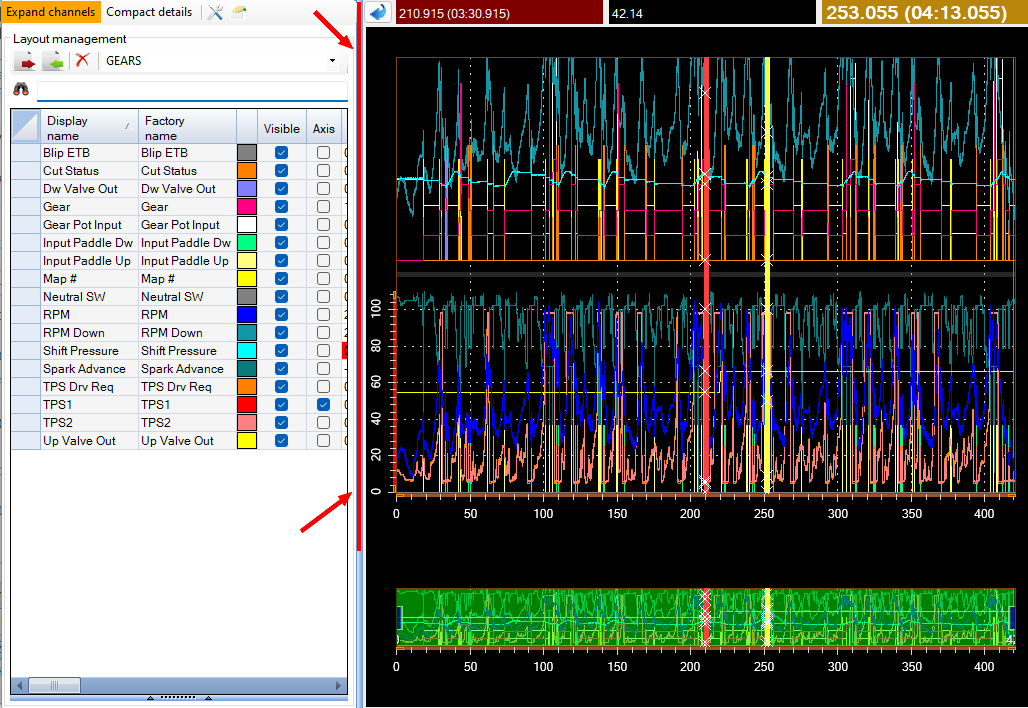


You will get the following  layout:

Click on the bar again to return to the channel list.

Was this helpful?

Yes  No
Related Articles
  • VERSION HISTORY
  • STRING FORMAT
  • APPENDICES
  • ASAP3
  • PRINT THE VALUES OF THE CALIBRATION VARIABLES
  • LINK ANALYSIS DISPLAY WITH ENGINE MAP

Didn't find your answer? Contact Us

Previously
SEGMENTS
Up Next
DISPLAY ORIENTATION
Copyright 2026 EFI Technology S.r.l. (Company subject to the management and coordination activities of MTA S.p.A.) All Rights Reserved.
We use cookies to make sure you can have the best experience on our site. If you continue to use this site we will assume that you approve our use of cookies.