• Home
  • Privacy policy
  • Italiano
  • English
  • Home
  • Privacy policy
  • Italiano
  • English
  • Software
    • ECT
      • ACKNOWLEDGEMENT
      • SYSTEM REQUIREMENTS
      • COMMUNICATION SCHEMES
      • DIRECTORY STRUCTURE
      • AVAILABLE TOOLS
      • INSTALLATION
      • GETTING STARTED
      • MAIN MENU
      • DEVICE EDITOR
        • ELF ORIENTED DEVICES AND NOT ELF ORIENTED DEVICES
        • STORAGE STRUCTURE OF THE DEVICE DATABASES
        • DEVICE LIST
          • CONTEXTUAL MENU IN THE DEVICE LIST
          • TOP BAR MENU
        • PAGE FOR EDITING THE VALUES IN THE DATABASE
          • TOP BAR MENU
          • MAIN - COMMUNICATION PARAMETERS AND OTHER SETTINGS
          • SCALINGS SECTION
          • INCREMENT SECTION
          • GROUPS SECTION
          • CHANNELS
          • CALIBRATION PARAMETERS
          • MEMORY MAP
        • COMMAND LINE USAGE
      • MEMORY INTERFACE
        • SEND (PC->ECU)
        • LEARN
        • RESET DIAGNOSTIC DATA
        • HDP/CRP MANAGER
        • MEMORYINTERFACE SETTINGS
      • DISPLAY
        • TYPES OF CONTAINERS
        • PROFILE STRUCTURE
        • CONTAINER MANAGEMENT
        • CONTROLS
        • MODIFICATION OF A CONTAINER
        • DATA RECORDING - F3 LOG
        • DISPLAY SETTINGS
      • CALIBRATION EDITOR
        • CALIBRATION TYPES
        • LOADING A CALIBRATION
        • WORKING WITH CALIBRATION EDITOR
        • CALIBRATION COMPARISON
        • PRINT THE VALUES OF THE CALIBRATION VARIABLES
        • SAVING CHANGES
        • DELETING A CALIBRATION FILE
        • CALIBRATION SETTINGS
      • ASAP3
      • CHARTING TOOL
        • LOADING A DATA FILE
        • MAIN MENU
        • CHANNEL LIST
        • CURSOR
        • SEGMENTS
        • DISPLAY LAYOUT
        • DISPLAY ORIENTATION
        • ZOOM
        • LINK ANALYSIS DISPLAY WITH ENGINE MAP
      • APPENDICES
        • STRING FORMAT
      • VERSION HISTORY

ASAP3

150 views 0

ASAP3

ASAP3 is a communication protocol used widely in the automotive industry to transfer data between dyno cells, engine management software, data loggers etc.  ASAP3 is mostly used for automated test environments.


ECT includes the ASAP3 communication protocol for the integration of engine electronic systems in a higher-order test bed system (AuSy – Automation System) via an engine electronic calibration system (MC System – Measurement Calibration – ECT). The actual integration occurs using a standardised serial RS232 data connection and uses the ASAP3 protocol that allows straightforward command and data exchange between the AuSy and MC system. Alternatively to the serial connection an Ethernet connection with TCP/IP protocol can be used. In this case, communication can take place between any PC on the test cell network.

Our basic system allows an easy exchange of data between the PC running ECT, communicating with the ECU, and the test cells software system.

The ASAP3 communication requires an update of our standard CAN communication interface plus an updated database for your ECU from OBR.


ASAP3 Options

Open the ECT main program and click on the option menu, marked in red on the right.
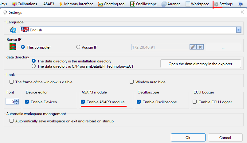
Tick the box to enable the ASAP3 option, click OK.

You will see a new tab added to the ECT tool’s main menu, ‘ASAP3’.


Serial port communication

Open the ASAP3 tab and click on the ‘Settings’ icon in the upper right-hand corner.

ASAP3 communication with the test cell software can be enabled using a serial RS232 port, you must use an USB Serial adaptor for this setting.

If you use the serial port, you must select your preferred data baud rate.

Anyway, serial links are slow, and this setting is not recommended.


Ethernet communication

Select the Ethernet option and connect your PC to the test cell with this connection.

Select the port address, typically either 22222 or 22226.  This port address must match the port address selected in your test cell’s ASAP3 section.  Data exchange using this option is much faster than a serial link.

Click OK to select the Ethernet communication.


 Establish ASAP3 Communication


Click the ASAP3 tab in the main ECT tool.

Click on ‘START’ and select the database for the ECU controlling your engine and click OK.
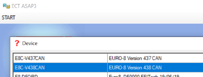
Enable the ASAP3 communication in your test cell’s computer system and you should now have an active data exchange between your ECU and your test cell.
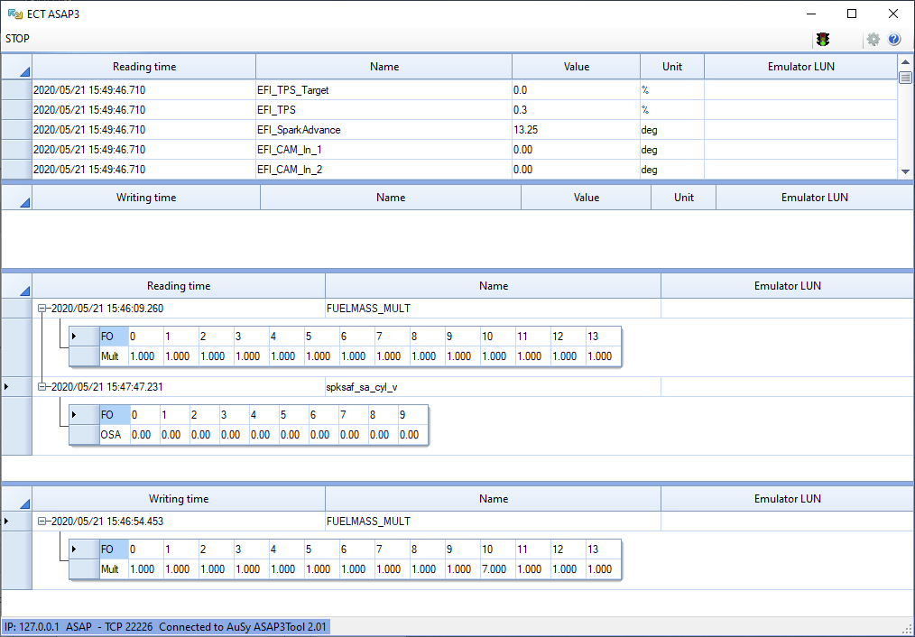
Communication is now established between the ECU and the test cell’s computer system.

Was this helpful?

Yes  No
Related Articles
  • VERSION HISTORY
  • STRING FORMAT
  • APPENDICES
  • PRINT THE VALUES OF THE CALIBRATION VARIABLES
  • LINK ANALYSIS DISPLAY WITH ENGINE MAP
  • DISPLAY ORIENTATION

Didn't find your answer? Contact Us

Previously
CALIBRATION SETTINGS
Up Next
CHARTING TOOL
Copyright 2026 EFI Technology S.r.l. (Company subject to the management and coordination activities of MTA S.p.A.) All Rights Reserved.
We use cookies to make sure you can have the best experience on our site. If you continue to use this site we will assume that you approve our use of cookies.