CALIBRATION
The calibration is a set of parameters that regulate the activity of the controller. Calibration data are placed in a memory area of the control unit which in function of the type of application can be programmed, modified and downloaded to the PC.
A typical example of calibration is the engine calibration that in the control units for automotive use contains the adjustable parameters relating to the operation of the motor (injection timing, advance, etc..). The ECT module for flashing and downloading the calibration is the Memory interface. The ECT module for modifying the calibration (in the control unit or file) is the Calibration editor module.
DESCRIPTOR
In order to parse the content of the calibration and display it to the user in an understandable way, you need to set a descriptor in the database of the device. The descriptor contains the list of variables of the calibration. For each variable you can specify the address, size, type, scale and other parameters needed for proper display of the variable in engineering format.
-
descriptor for the main calibration (built-in type)
-
descriptor for setup calibration setup (built-in type)
-
descriptor for learn calibration (built-in type)
- a variable number of custom descriptor types each identified by a file extension
There can be multiple descriptors for each type . If multiple descriptors are defined for one single type of descriptors, for each use of the descriptor to parse the content of a calibration, you will be asked to choose from a list, the descriptor you want.
In a descriptor, variable addresses are used as offset relative to the start address of the descriptor that is compulsorily specified when defining the descriptor.
This is because a descriptor can be used to parse several calibrations having the same structure but programmed to different addresses. The start address for programming and online editing of each of these calibrations, is specified in the memory map.
Interpretation process of the variables of a calibration:
-
Loading of the descriptor and offset calculation based on the start address of the descriptor of each variable contained in the descriptor. The variable whose address corresponds to the address stated as the beginning of the descriptor will have offset 0 and so on.
-
Loading raw data buffer of the calibration corresponding to the memory area declared in the memory map for this calibration. Regardless of the downloading address, the byte of the buffer with index 0 will coincide with the first byte of the calibration.
-
Calculation of the engineering value of each variable specified in the descriptor using data from the buffer calibration that have index equal to the offset calculated for the variable descriptor taken into account.
SUBSECTION: DESCRIPTORS
In this subsection you can view and edit descriptors .
Current descriptor
The descriptor selected in this subsection is considered as the current descriptor. The variables listed in the subsections limits, values, curves, maps, cuboids, shared axes are those that belong to the current descriptor.
Therefore :
-
The contents of these subsections varies with the current descriptor.
-
Deleting a descriptor involves the elimination of variables that belong to it.
-
The insertion or deletion of a variable in these subsections only affects the current descriptor. In the sections scaling and groups, the variables related to current scaling or to the current group are highlighted in white if they belong to the channel list or the current descriptor, and are highlighted in gray if they belong to a descriptor different from the current descriptor.
The current descriptor makes sense only within the application deviceeditor .
Descriptor .DES
The .DES files are text files used in previous versions of ECT as descriptors of the calibrations .
They contained information about offset, name, scaling, group for each variable.
In ECT_DN they are replaced by tables in the database of the device, but you can import descriptors from DES file.
To edit the contents of this subsection, enable ‘Expert Mode’ in the top-most toolbar.
COMMAND BAR

Navigation commands
Allow you to move through the records in the database table that contains the descriptors .
Add command
Adds a new descriptor.
The user is prompted to specify :
-
Name of the new descriptor. It must not already exist.
-
Type of calibration to describe
-
Main
-
Learn
-
Setup
- Custom
-
At the end of the input stage ECT creates a new empty descriptor .
In case the device is NOT ELF-oriented it is not necessary to specify additional data
In case the device is ELF-oriented it is necessary to specify :
-
The variable that sets the start address of the descriptor
To specify the variable use the command double click the text box that holds the variable name.
-
The maximum size of the memory area described by the descriptor .
To specify the size, type the value in the ‘Maximum size’ box. Allowed formats are the decimal format (pure number) and hexadecimal notation 0xHHH where HHH is the value in hexadecimal.
- Only in case the new descriptor is of a custom type, it is necessary to specify the extension of the calibration files that will be interpreted with this descriptor. To specify the extension, double-click the text box next to the “Extension” label.
To add items to the descriptor, use the sub-sections values, curves and maps. Access to these subsections is only possible after you have completed the data entry in the section ‘Descriptors’
Delete command
Allows the deletion of the selected descriptor.
Double click the text box that holds the variable name
It allows you to set the start address of the descriptor. Available only for ELF-Oriented devices.
The command opens a page that lists the variables in the ELF file. The user must select from this list the variable at the beginning of the descriptor and press the Ok button.
At the end of the operation, ECT shows the address and the name of the variable.
Import variables form .A2L file
The command is active only for ELF-oriented devices and only if the ELF file is present on disk.
Allows you to import calibration variables from an A2L file.
The user is prompted to specify an .A2L file and is then asked whether to import only the variables present in the ELF file.
After the import is complete, a report listing the imported variables is displayed.
Import descriptor form .DES file
The command is active only for ELF-oriented devices and only if the ELF file is present on disk.
The command lets you to import a descriptor from .DES file.
The user is prompted to specify a file .DES and the prefix of the variables if the variables share a common part as in the case they are part of a single structure. The prefix is especially useful for ELF-Oriented devices. The prefix can be omitted.
SUBSECTION: FORMULAS
PURPOSE OF FORMULAS
Formulas are an alternate scaling method.
Like scalings they consist of a set of parameters used to derive the engineering value from a binary value.
Unlike scalings, formulas depend on other calibration values and thus they are meaningful for the current calibration only.
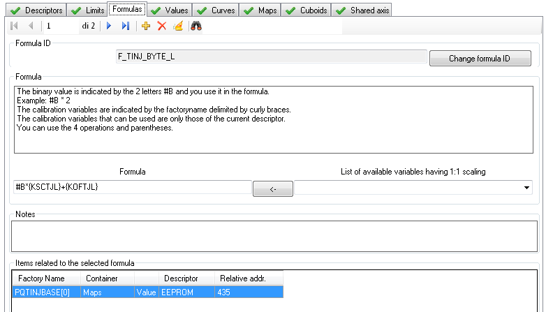
A formula is an expression where the binary value is represented as #B and calibration variables as {factoryname}
An example of formula is:
#B*{KSCTJL}+{KOFTJL}
#B is the binary value
KSCTJL is the factoryname of a calibration value
KOFTJL is the factoryname of a calibration value
You can combine as many variables as you like.
You can use the 4 operations and parentheses
COMMAND BAR
Navigation commands
These commands allow you to move through the records in the database table that contains the formulas.
Add command
Used to add a new entry to the list of formulas.
This command opens a dialog where you can specify the name of the new formula. The default name can be changed but it must not be equal to another name already used. If the name you typed is the same as an existing name, ECT alerts you with a message.
Delete command
Used to delete an entry from the list of formulas.
The command is rejected if the formula is used in the database as attribute of a calibration variable.
Delete unused items
This command checks if there are unused formulas and deletes them.
Search command
In the text area next to the binoculars, you can specify the ID of a formula to be searched.
The research starts when you press the Enter key. A further press of the Enter key allows you to search for the next occurrence. At the last event, by pressing again the Enter key, you return to the first occurrence.
The command supports wildcards
FORMULA ID AREA
This area contains the unique formula ID display box and the ID rename command. The rename command is accepted only if the new name does not already exist.
FORMULA AREA
In this area you can see and edit the formula. If you want to add the factoryname of a calibration value you can just type it or select it from the list on the right side of the input box.
RELATED ITEMS AREA
This area contains the list of calibration variables that use the selected formula.
If this list is empty you can use the command ‘Delete’.
SUBSECTION: CALIBRATION VALUES
In this subsection you can view and edit the numeric variables to 1, 2 or 4 bytes, text variables, the variable ‘name and date’ (special case of string variable), the variable checksum.
COMMAND BAR
ELF-Oriented devices
Navigation commands
Allow you to move through the records in the database table that contains the values.
Append items from another device
It lets you integrate the values of the current descriptor with the values imported from another device .
You are asked to :
-
Specify the file path of the other device
-
Specify whether to import only the variables that have matching variables in the ELF of your current device. If you choose to import the variables that do not have matching variables in the ELF of the current device, these variables will be NOT validated .
-
Specify whether to extend the import to variables that belong to other lists (curves, maps, cuboids). If you accept this proposal, the variables will be placed in the respective list.
It can be served a warning if ECT notes that the name of the device descriptor chosen for the import is different from the name of the current descriptor .
When finished, a message notifies you how many items were imported.
Delete command
It lets you delete the selected value.
Inherit properties from
It lets you modify the properties of the selected value by inheriting the properties of another value.
Manage values with current ELF
-
The command can only be used in the ELF oriented devices .
It opens the ‘ELF items check’ page where you can align the database variables to the contents of ELF files .
On this page you can delete and add variables.
See section VALIDATION.
Search command
In the text area next to the binoculars, you can specify the ID of a variable to be searched .
The research starts when you finish press the Enter key . A further press of the Enter key Allows you to search for the next occurrence . At the last event , again by pressing the Enter key, you return to the first occurrence.
The command supports wildcards
Wildcard filter. Case sensitive
Alternative command to the previous one that allows you to reduce the list of visible channels based on the set filter.
NON-ELF oriented devices
Navigation commands
Allow you to move through the records in the database table that contains the values.
Command add
Adds a new variable.
The user is prompted to specify the variable offset from the beginning of the descriptor (which corresponds to the offset from the start of calibration). As default offset is proposed the first free offset after the last descriptor variable (the variable could also belong to the lists curves, maps, cuboids).
The user can change this offset.
It creates a variable at the specified offset. The user must then fill out the complete data of the variable in the Properties area .
Command delete
It lets you delete of the selected value.
Inherit properties from
It lets you modify the properties of the selected value ny inheriting the properties of another value.
Search command
In the text area next to the binoculars, you can specify the ID of a variable to be searched .
The research starts when you finish press the Enter key. A further press of the Enter key Allows you to search for the next occurrence . At the last event , again by pressing the Enter key, you return to the first occurrence .
The command supports wildcards
Wildcard filter. Case sensitive
Alternative command to the previous one that allows you to reduce the list of visible channels based on the set filter.
TABLE AREA
Contains the complete list of calibration values with all their relevant data.
Each line refers to a variable.
The read-only columns background color is gray, the editable columns background color white .
The editable fields can be changed by typing text directly into the cells of the grid.
GROUPS AREA
The group membership is used in the calibrationeditor module. It makes it possible to display a structured list of values in the section ‘Calibration parameters’ of calibrationeditor.
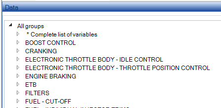
The group area group contains commands for managing groups associated with the current calibration value.
It is divided into 2 parts.
The list on the left shows the groups that are already associated with the current variable.
The list on the right shows the groups defined in the current device.
The arrows placed at the center allow you to associate an available group to the variable (arrow from right to left) or remove the association of a variable previously associated (arrow from left to right).
A single variable can also be associated with more than one group or no group.
The variables of type ‘Name and date’ and type ‘Checksum’ can not be associated with a group and for this reason during the viewing and editing of these types of variables, the group area is hidden.
PROPERTIES AREA
This area lists the properties of the variable divided into subgroups.
Some properties are editable, some are read-only.
Some properties can be changed if the device is NOT ELF-oriented while they are read-only if the device is ELF-oriented because they depend on the data obtained from the ELF file.
SUBGROUP: MAIN
Contains:
Factory name of the variable
It is editable for devices that are NOT ELF-oriented while it is read-only for ELF-oriented devices because it matches the name of a variable of application software obtained from the ELF file.
Type of the variable
-
Numeric variable
-
Text variable
-
‘Name and date’ variable (special case of variable text )
-
Checksum variable
Notes :
‘Name and date’ variable
-
There must be the ONE variable ‘name and date’ for the main and setup calibrations.
-
There must be NO variable ‘name and date’ for learn calibrations.
-
The variable ‘name and date’ is used by calibrationeditor to derive the name of the calibration and can be changed with specific command .
-
In calibrationeditor the content of variable ‘name and date’ is only shown on the first page and can not be added to a group.
‘Checksum’ variable
-
There can only be one variable ‘checksum ‘ in a descriptor .
-
The content of the variable ‘checksum ‘ is recalculated automatically by calibrationeditor when saving to a file or confirming your changes online.
-
The variables involved in the calculation of the checksum are stored in the addresses lower than the address of the checksum variable itself.
-
In calibrationeditor the content of the variable ‘checksum’ is only shown on the first page and can not be added to a group.
Type of checksum calculation
By selecting the checksum a field to select the type of checksum calculation is enabled.
There are 3 possible alternatives according to the specifications of the designer.
-
EFI standard
-
16 -M1
- 16-CCITT-1021
Address value (only ELF-Oriented devices)
Read-only because it corresponds to the address of a variable of application software obtained from the ELF file .
Variable offset in bytes
It is editable for NON ELF-oriented devices while it is read-only for ELF-oriented devices because it corresponds to the difference between the current variable address and the start address of the descriptor.
Size in bytes of the variable
It is editable for NON ELF-oriented devices while it is read-only for ELF-Oriented devices because it matches the name of a variable of application software obtained from the ELF file.
Signed
Indicates whether the variable is 2’s complement. It is editable for NON ELF-oriented devices while it is read-only for ELF-oriented devices because it matches the type of the variable of application software obtained from the ELF file.
Float
Indicates whether the variable holds a floating-point value
SUBGROUP: NAMES
Contains:
Display identifier
Label used to identify the variable in calibrationeditor. The data is exported to the A2L file .
Description
Label used to identify the variable in calibrationeditor in display lists .
ASAP3 Name
Name used in ASAP3 communication between ECT and the test bench. It must match the name used in the test bench.
The ASAP3 export uses the address read from ELF.
Do not select this option (default) if you are using the address of the start of the memory area linked to the calibration defined in the memorymap section of the device editor plus the variable offset to read the variable from the control unit.
Select this option if you are using the address of the elf variable to read the variable from the control unit.
SUBGROUP: VISUALIZATION
Subgroup irrelevant and invisible to variables of type ‘name and date’ and ‘checksum’.
Contains:
Type of representation
The alternatives are:
- decimal
- hexadecimal without byte order (the byte order defined for the device is ignored)
- hexadecimal with byte order (the byte order defined for the device is applied)
- binary
Display Format
A string used to format the engineering value. (See Formatting strings )
Unit
A string used to indicate the units (or other information ) .
SUBGROUP: SCALED VALUES
Subgroup irrelevant and invisible to variables of type ‘name and date’, ‘Text’ and ‘checksum ‘.
Contains:
Scaling ID
Unique ID that identifies the scaling used to obtain the engineering value from binary value read from this variable .
The button to the left of the ID gives you access to the edit page of the scaling. The button to the right of the ID allows you to select another scaling from the list of available scaling .
Min value and Max value
The minimum and maximum engineering values obtainable from the variable according to the current scaling. Read-only values.
Custom Min value and Custom Max value The minimum and maximum engineering values imposed by the user.
These values are used to limit the minimum and maximum values in the editing. (Calibrationeditor)
SUBGROUP: EXTERNAL VISIBILITY
Visible only for ELF-Oriented devices.
Contains:
Export to ASAP2
Sets the variable as exportable to ASAP2
Open variable
Makes the channel available in the display module even if the device has been protected with password.
SUBGROUP: NOTES
Notes
Notes that the user can freely add.
If the “Representation Type” setting is “Binary,”
each line of the notes text becomes the label associated with each bit of the variable.
By convention, the first line will be the label for bit 0, the second will be the label for bit 1, and so on.
When the user requests to change the variable’s value, a grid is displayed showing the label and the value to be changed for each bit.
SUBSECTION: CALIBRATION CURVES
In this subsection you can view and edit the variables that are structured in one-dimensional lists.
-
Curve with 1 byte values
-
Curve with 1 byte values – threshold type break points
- Shared axis. 1-byte elements
- Shared axis. 1-byte elements – threshold breakpoint
- Curve without axis. 1-byte elements
-
Curve with 2 bytes values
-
Shared axis. 2-byte elements
-
Curve without axis. 2-byte elements
COMMAND BAR
ELF-Oriented devices
Navigation commands
They let you move through the records in the database table that contains the values.
Append items from another device
It lets you integrate the curves of the current descriptor with curves imported from another device.
You are asked to :
-
Specify the file path of the other device
-
Specify whether to import only the variables that have matching variables in the ELF of your current device. If you choose to import the variables that do not have matching variables in the ELF of the current device, these variables will be NOT validated .
-
Specify whether to extend the import to variables that belong to other lists (curves, maps, cuboids). If you accept this proposal, the variables will be placed in the respective list.
It can be served a warning if ECT notes that the name of the device descriptor chosen for the import is different from the name of the current descriptor.
When finished, a message notifies you how many items were imported.
Command delete
It lets you delete the selected curve.
Inherit properties from
It lets you modify the properties of the selected curve inheriting the properties of another curve.
Validate curves
The command can only be used with ELF-Oriented devices.
It opens the ‘ELF items check ‘ where you can align the database variables to the contents of ELF files.
On this page you can delete and add variables.
See VALIDATION section.
Search command
In the text area next to the binoculars, you can specify the ID of a variable to be searched.
The research starts when you finish press the Enter key. A further press of the Enter key Allows you to search for the next occurrence. At the last event, again by pressing the Enter key, you return to the first occurrence.
The command supports wildcards
Wildcard filter. Case sensitive
Alternative command to the previous one that allows you to reduce the list of visible channels based on the set filter.
NON-ELF oriented devices
Navigation commands
They let you move through the records in the database table that contains the values.
Add command
It adds a new variable.
The user is prompted to specify the variable offset from the beginning of the descriptor (which corresponds to the offset from the start of calibration). As default offset is proposed the first free offset after the last descriptor variable (the variable could also belong to the value lists, maps, cuboids ).
The user can change this offset.
It creates a variable at the specified offset. The user must then fill out the complete data of the variable in the Properties area.
Delete command
It lets you delete the selected curve.
Inherit properties from
It lets you modify the properties of the selected variable by inheriting the properties of another variable.
Search command
In the text area next to the binoculars, you can specify the ID of a variable to be searched.
The research starts when you finish press the Enter key . A further press of the Enter key Allows you to search for the next occurrence . At the last event , again by pressing the Enter key, you return to the first occurrence.
The command supports wildcards
Wildcard filter. Case sensitive
Alternative command to the previous one that allows you to reduce the list of visible channels based on the set filter.
GRID AREA
It contains the complete list of calibration curves with all their relevant data.
Each line refers to a variable.
The read-only columns background color is gray, editable columns background color is white. The editable fields can be changed by typing text directly into the cells of the grid.
GROUPS AREA
The group membership is used in the calibrationeditor module. It makes it possible to display a structured list of values in the section ‘Calibration parameters’ of calibrationeditor.
The groups area contains commands for managing groups associated with the current variable.
It is divided into 2 parts.
The list on the left shows the groups that are already associated with the current variable.
The list on the right shows the groups defined in the current device.
The arrows placed at the center allow you to associate an available group to the variable (arrow from right to left) or remove the association of a variable previously associated (arrow from left to right).
A single variable can also be associated with more than one group or no group.
PROPERTY AREA – HOME

This area lists the properties of the variable divided into subgroups.
Some properties are editable, some are read-only.
Some properties can be changed if the device is NOT ELF-oriented while they are read-only if the device is ELF-oriented because they depend on the data obtained from the ELF file.
SUBGROUP: MAIN
Contains:
Factory name of the variable
It is editable for devices that are NOT ELF-oriented while it is read-only for ELF-oriented devices because it matches the name of a variable of application software obtained from the ELF file.
Type of the variable
For 1 byte variable arrays :
-
Curve with 1 byte values
-
Curve with 1 byte values – threshold type break points
- Curve with shared axis. 1-byte elements
- Curve with shared axis. 1-byte elements – threshold breakpoint
- Curve without axis. 1-byte elements
For 2 bytes variable arrays :
-
Curve with 2 bytes values
-
Curve with shared axis. 2-byte elements
-
Curve without axis. 2-byte elements
Address (only ELF-oriented devices)
Read-only because it corresponds to the address of a variable of application software obtained from the ELF file .
Variable offset in bytes
It is editable for NON ELF-oriented devices while it is read-only for ELF-oriented devices because it corresponds to the difference between the current variable address and the start address of the descriptor.
Size in bytes of the variable
It is editable for NON ELF-oriented devices while it is read-only for ELF-Oriented devices because it matches the name of a variable of application software obtained from the ELF file.
Use maximum size (only ELF-oriented devices)
Specifies whether the validator must assign to the variable the maximum size of the corresponding array declared in the ELF. This parameter is useful if after recompiling the ELF, the size of the array that generates the curve has changed. If the parameter is active, any change of the size of the array in the ELF is automatically reflected in the corresponding curve described in the database at the time of subsequent validation.
Signed
Specifies whether the variable is 2’s complement. It is editable for NON ELF-oriented devices while it is read-only for ELF-oriented devices because it matches the type of the variable of application software obtained from the ELF file.
float
Specifies whether the variable holds a floating-point value
Size of a value in bytes
Shows the size of the single item of the curve.
Read-only parameter.
Equispaced
It lets you define whether the curve is equally spaced .
Applicable only to the type of curve with 1-byte elements . A equally spaced curve has no custom breakpoint. The memory area corresponding to the curve contains only the values of the curve. The values of the breakpoints are obtained with a mathematical formula splitting equally the engineering extension derived from the breakpoints scaling parameters.
Theoretical size
Total size of the memory occupied by the curve based on the size of the single element of the array and the number of breakpoint . Must match the declared size of the array. Serves to highlight errors in the definition of the number of breakpoints .
SUBGROUP: NAMES
Contains:
Display identifier
Label used to identify the variable in calibrationeditor. The label is exported to the A2L file .
Description
Label used to identify the variable in calibrationeditor in display lists .
ASAP3 Name
Name used in ASAP3 communication between ECT and the test bench. It must match the name used in the test bench.
The ASAP3 export uses the address read from ELF.
Do not select this option (default) if you are using the address of the start of the memory area linked to the calibration defined in the memorymap section of the device editor plus the variable offset to read the variable from the control unit.
Select this option if you are using the address of the elf variable to read the variable from the control unit.
SUBGROUP: EXTERNAL VISIBILITY
Visible only for ELF-Oriented devices.
Contains:
Export to ASAP2
Sets the variable as exportable to ASAP2
Open variable
Makes the channel available in the display module even if the device has been protected with password.
SUBGROUP: NOTES
Notes
Notes that the user can freely add.
PROPERTY AREA – VALUES OF THE CURVE

Contains the parameters to adjust the display of the values of the curve in calibrationeditor .
SOTTOGRUPPO: MAIN
Label
Label used to identify the values of the curve in the display grid in calibrationeditor .
Increment ID
A unique ID within the device that identifies the type of increment that can be used to modify curve values in the Calibration Editor.
The increment must be selected from the list of available increments.
SUBGROUP: SCALED VALUES
Scaling ID
Unique ID that identifies the scaling used to obtain the engineering value from binary value read from this variable.
The button to the left of the ID gives you access to the edit page of the scaling. The button to the right of the ID allows you to select another scaling from the list of available scaling .
Min value and Max value
The minimum and maximum engineering values obtainable from the variable according to the current scaling. Read-only parameters .
Custom Min value and Custom Max value
The minimum and maximum engineering values imposed by the user. These values are used to limit the minimum and maximum values in the editing. (Calibrationeditor)
SUBGROUP: VISUALIZATION
Display Format
A string used to format the value engineering . (See Formatting strings)
Units
A string used to specify the units (or other information ) .
SUBGROUP: RELATED CHANNEL
Related channel
The related channel establishes a relationship between the list of values or a list of breakpoints and a channel. A channel related to the list of values must be a channel configured as a potentiometer. If you use a potentiometer channel in the display module to perform the engine mapping, ECT requires to specify a descriptor and then searches within the descriptor for a curve or map whose values have the ‘related channel’ field set equal to the potentiometer channel. In this way ECT is able to know which curve or map is the target of the engine mapping operations. (Display)
Button that loads the channel list and allows the selection of the related channel .
Once loaded the connected channel, ECT shows the channel name and the ID of the scaling of the channel. This allows you to compare the scaling of the related channel to the scaling of the value?. If the scalings are different, the ID of the scaling of the related channel is shown on orange background. It is a visual warning to report a situation that is allowed but must be checked carefully.
This button deletes the link to the channel.
PROPERTY AREA – CURVE BREAKPOINT

Contains the parameters to adjust the view of the breakpoint of the curve in calibrationeditor .
SUBGROUP: MAIN
Factory name
-
only for curves with shared axes
-
only for ELF-Oriented devices
Factory name of the axis to use as a shared list of breakpoints .
Label
Label used to identify the breakpoint of the curve in the display grid in calibrationeditor. Read-only parameter if breakpoints come from a shared axis.
Breakpoint count
Breakpoints count. The value must be calculated based on the size of the array, the type of curv, the size of the single element and the fact that the curve is equispaced or not.
Example:
-
An array of 32 bytes, NOT equispaced, with 1 byte items, will have 16 breakpoints . (16 1 byte breakpoints ?+ 16 1 byte values )
-
An array of 32 bytes, equispaced, with 1 byte items, will have 32 breakpoints (32 1 byte values + 32 0 bytes breakpoints because virtual, calculated with mathematical formula .)
-
An array of 32 bytes, NOT equispaced, with 2 bytes items, will have 8 breakpoints . (8 2 bytes breakpoints + 8 2 bytes values .
-
An array of 32 bytes, with 1-byte items and breakpoints form a shared axis will have 32 breakpoints (32 1 byte values ?+ 32 0 byte breakpoint because they belong to the variable that defines the shared axis.)
If the number of breakpoints is not correct, in the home page, the background of the field that contains the size of the curve will be highlighted in red to show that the actual size of the curve and the theoretical size do not match.
Read-only parameter if breakpoints come from a shared axis.
Monotonicity
There are two possible choices:
- Increasing monotonicity (default). Each break point must be greater than or equal to the breakpoint that precedes it.
Strictly increasing monotonicity. Each break point must be greater than the breakpoint that precedes it.
SUBGROUP: SCALED VALUES
Scaling ID
Unique ID within the device which identifies the scaling to use to get the engineering value from the binary value of this breakpoint.
The button to the left of the ID gives you access to the edit page of the scaling.
The button to the right of the ID allows you to select another scaling from the list of available scaling .
Read-only parameter if breakpoints come from a shared axis.
Min value and Max value
The minimum and maximum engineering values obtainable from the variable according to the current scaling. Read-only parameters .
SUBGROUP: VISUALIZATION
Display Format
A string used to format the engineering value. (See Formatting strings ) Read-only parameter if breakpoints come from a shared axis.
Units
A string used to specify the units (or other information ) . Read-only parameter if breakpoints come from a shared axis.
SUBGROUP: RELATED CHANNEL
Related channel
The related channel establishes a relationship between the list of values or a list of breakpoints and a channel. A channel related to a the breakpoint list serves as a support for breakpoints animation while viewing the online calibration. The value read from the related channel allows ECT to indicate the active breakpoint (Curves visualization in Calibrationeditor and Display modules).
Button that loads the channel list and allows the selection of the related channel.
Once loaded the related channel, ECT shows the channel name and the ID of the scaling of the channel. This allows you to compare the scaling of the related channel to the scaling of the values?. If the scalings are different, the ID of the scaling of the connected channel is shown on orange background. It is a visual warning to report a situation that is allowed but must be checked carefully.
This button deletes the link to the channel.
Read-only parameter if breakpoints come from a shared axis.
SUBSECTION: CALIBRATION MAPS
In this subsection you can view and edit the variables that are structured in two-dimensional arrays.
-
Map – 1-byte elements
-
Map – threshold breakpoint – 1-byte elements
-
Map with shared axes – 1-byte elements
-
Map with shared axes – threshold breakpoint – 1-byte elements
-
Map without axes – 1-byte elements
- Map – 2-byte elements
- Map with shared axes – 2-byte elements
- Map without axes – 2-byte elements
The subsection is similar to subsection ‘Calibration curves’. Unlike the curves, maps have a second breakpoint that is defined in a similar way to the first.
SUBSECTION: CALIBRATION CUBOIDS
In this subsection you can view and edit the variables that are structured in three-dimensional arrays.
-
Cuboid – 1 byte elements
The subsection is similar to subsection ‘Calibration curves’. Unlike the curves, cuboids have a second breakpoint that is defined in a similar way to the first.
The cuboids are supported only for backward compatibility. They consist of a series of two-dimensional maps streak and an extra byte that contains the information on the third breakpoint. The value of the third breakpoint indicates which is the active map.
SUBSECTION: SHARED AXES
The management of shared axis is present only in the ELF-oriented devices.
In this subsection you can view and edit shared axes.
-
1 byte shared axis
Shared axis with 1 byte values
-
2 byte shared axis
Shared axis with 2 bytes values
COMMAND BAR
See subsection ‘Calibration curves’
GRID AREA
See subsection ‘Calibration curves’
GROUPS AREA
See subsection ‘Calibration curves’
PROPERTY AREA – HOME
See subsection ‘Calibration curves’
SUBGROUP: MAIN
Contains:
Factory name of the variable
Read only parameter. It matches the name of a variable of application software obtained from the ELF file.
Type of the variable
-
1 byte shared axis shared axis with 1 byte values
-
2 bytes shared axis shared axis with 2 bytes values
Address (ELF-oriented devices only)
Read-only because it corresponds to the address of a variable of application software obtained from the ELF file .
Variable offset in bytes
Read-only parameter because it corresponds to the difference between the current variable address and the start address of the descriptor.
Size in bytes of the variable
Read-only parameter because it matches the name of a variable of application software obtained from the ELF file.
Use maximum size (only for ELF oriented devices)
Specifies whether the validator must assign to the variable the maximum size of the corresponding array declared in the ELF. This parameter is useful if after recompiling the ELF, the size of the array that generates the curve has changed. If the parameter is active, any change of the size of the array in the ELF is automatically reflected in the corresponding curve described in the database at the time of subsequent validation.
Signed
Specifies whether the variable is 2’s complement. It is editable for NON ELF-oriented devices while it is read-only for ELF-oriented devices because it matches the type of the variable of application software obtained from the ELF file.
Float
Indicates whether the variable holds a floating-point number
Size of a value in bytes
Shows the size of the single item of the curve.
Read-only parameter .
Theoretical size
Total size of the memory occupied by the curve based on the size of the single element of the array and the number of breakpoint . Must match the declared size of the array. Serves to highlight errors in the definition of the number of breakpoints .
SUBGROUP: NAMES
See subsection ‘Calibration curves’
SOTTOGRUPPO: EXTERNAL VISIBILITY
See subsection ‘Calibration curves’
PROPERTY AREA – BREAKPOINT

Contains the parameters to adjust the view of the breakpoint of the shared axis in calibrationeditor .
SOTTOGRUPPO: MAIN
Label
Label used to identify the breakpoint in the display grid in calibrationeditor.
Breakpoint count
Breakpoints count. The value must be calculated based on the size of the array, and the size of the single element. BP_count = VAR_overall_size / VAR_single_value_size
If the number of breakpoints is not correct, in the home page, the background of the field that contains the size of the axis will be highlighted in red to show that the actual size of the axis and the theoretical size do not match.
SUBGROUP: SCALED VALUES
Scaling ID
Unique ID within the device which identifies the scaling to use to get the engineering value from the binary value of this breakpoint.
The button to the left of the ID gives you access to the edit page of the scaling.
The button to the right of the ID allows you to select another scaling from the list of available scaling .
Min value and Max value
The minimum and maximum engineering values obtainable from the variable according to the current scaling. Read-only parameter.
Min custom value and max custom value
The minimum and maximum engineering values set by the user. These values are used to restrict the value range when breakpoints are being edited. (Calibrationeditor)
Monotonicity
Monotonicity of the BP sequence. Always increasing.
Display Format
A string used to format the engineering value. (See Formatting strings )
Units
A string used to specify the units (or other information ) .
SUBGROUP: RELATED CHANNEL
Related channel
The related channel establishes a relationship between the list of values or a list of breakpoints and a channel. A channel related to a the breakpoint list serves as a support for breakpoints animationwhile viewing the online calibration. The value read from the relsted channel allows ECT to indicate the active breakpoint (Curves visualization in Calibrationeditor and Display modules).
Button that loads the channel list and allows the selection of the related channel.
Once loaded the related channel, ECT shows the channel name and the ID of the scaling of the channel. This allows you to compare the scaling of the related channel to the scaling of the values?. If the scalings are different, the ID of the scaling of the connected channel is shown on orange background. It is a visual warning to report a situation that is allowed but must be checked carefully.
This button deletes the link to the channel.