The term channel is defined as a variable of the application sw, readable by ECT. These variables are used inside the display module to compose window where the user can read real-time data acquired from the unit. The data can be represented in various forms (text, led, potentiometer) with different scalings and with different graphical attributes.
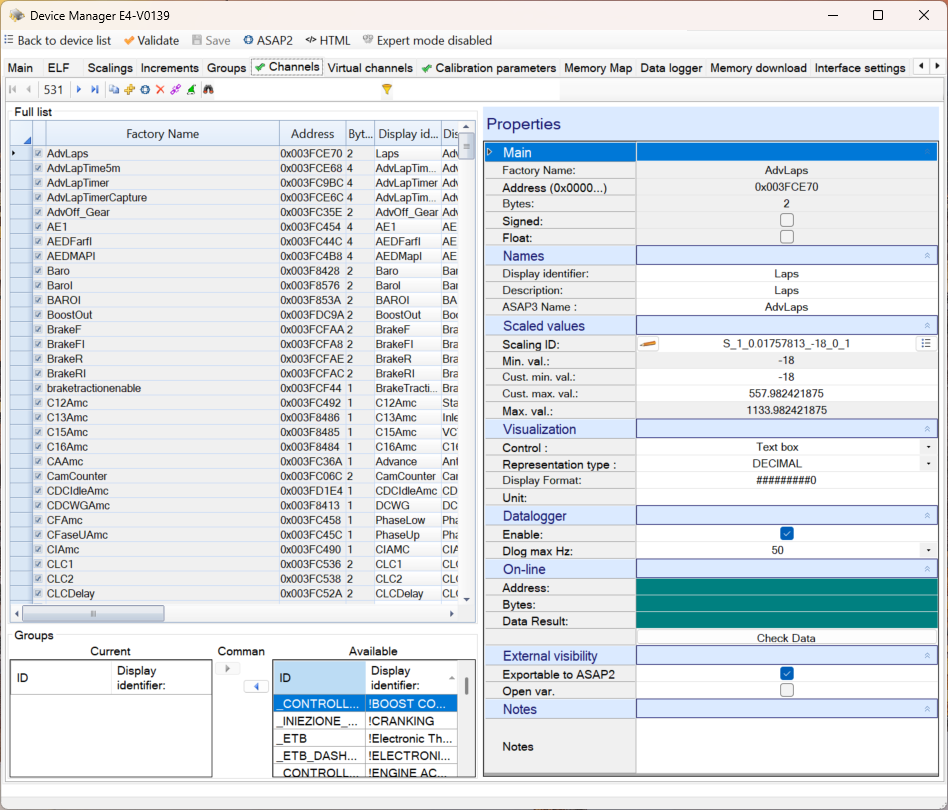
Prerequisite for channel management is the proper configuration in this section of deviceeditor.
COMMAND BAR

Navigation commands
Allow you to move through the records in the database table that contains the channels.
Add comand – static table device only
It can be used to append one or more new channel
-
User is asked to specify how many channels to add
-
User is asked to specify which existing channel should be used as a model for the creation of new channels and which attributes of the source channel must be inherited by the new channels.
Command add elements from another device – ELF oriented device only
The command can only be used in the ELF oriented devices. Adds channels defined in another device.
User is asked to:
-
Locate another database device.
-
Specify if he wants to import only those items that have a match in the ELF file variables in the current device (alternatively will be imported without distinction all channels that are missing in the current device even if they can not be validated with the current device ELF)
When finished, a message will notify how many channels were imported.
Import channels from A2l file
The command can only be used in the ELF oriented devices. Adds channels defined in a A2L file.
User is asked to:
-
Locate an A2L file.
-
Specify if he wants to import only those items that have a match in the ELF file variables in the current device (alternatively will be imported without distinction all channels that are missing in the current device even if they can not be validated with the current device ELF)
When finished, a message will notify how many channels were imported.
Delete comand
Allows the deletion of the selected channel.
If the device is NOT ELF oriented, you can delete only the last channel in the list.
Manage links to channels in other contexts
If there are links to channels in other contexts, such as channels defined as ‘reference channels’ in curves and maps, a channel may be deleted from the channel management page, but a broken link to the deleted channel name remains in the curve or map.
This command replaces the channel names in broken links with existing channel names. For each broken channel, you can select a replacement from the list of real channels or maintain the current state by selecting the virtual channel _NOCHANGE.
Inherit properties from
Allows you to modify the properties of the selected channel by inheriting the properties of another channel.
Manage channels with current ELF
-
The command can only be used with ELF oriented devices.
Opens the ‘Validate with current ELF’ where you can align the database variables to the contents of ELF files.
On this page you can delete and add channels.
See section VALIDATION.
Search command
In the text area next to the binoculars, you can specify the ID of a channel to be searched.
The research starts when you press the Enter key. A further press of the Enter key allows you to search for the next occurrence. At the last event, by pressing again the Enter key, you return to the first occurrence.
The command supports wildcards
Wildcard filter. Case sensitive
Alternative command to the previous one that allows you to reduce the list of visible channels based on the set filter.
TABLE AREA
It contains a complete list of channels and all related relevant data.
Each line refers to a channel.
The read-only columns background color is gray, editable columns background color is white.
The editable fields can be changed by typing text directly into the cells of the grid.
GROUP AREA
The group membership is used in the display module. It makes it possible to display a structured list of channels in the channel selection page. If no group is used, the channels are shown in a single list.
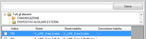
The group area contains commands for managing groups associated with the current channel.
It is divided into 2 parts.
The list on the left shows the groups that are already associated with the current variable.
The list on the right shows the groups defined in the current device.
The arrows placed at the center allow you to associate an available group to the channel (arrow from right to left) or remove the association of a channel previously associated (arrow from left to right).
A single channel can also be associated with more groups or no group.
PROPERTY AREA
This area lists the properties of the channel divided into subgroups.
Some properties are editable, some are read-only.
Some properties can be changed if the device is NOT ELF-oriented while they are read-only if the device is ELF-oriented because they depend on the data obtained from the ELF file.
SUBGROUP: MAIN
It contains:
Factory name of the variable
It is editable for devices that are NOT ELF-oriented while it is read-only for ELF-oriented devices because it matches the name of a variable of application software obtained from the ELF file.
Variable address (only for ELF-oriented devices)
Read-only because it corresponds to the address of a variable of application software obtained from the ELF file.
Variable index (only devices that are NOT ELF-oriented)
Read-only because it corresponds to the 0-based position of the channel in the channel list. For NON ELF-oriented devices this index is used to calculate an offset using a mathematical formula. By adding the calculated offset to a known address of the memory of the control unit, ECT obtains the static table address of the variable. Once it has calculated this address, ECT is able to request from the unit the data stored at that address. The data contains information on the variable including the address of the variable in the control unit, the size of the variable and the 2’s complement attribute.
Size of the variable in bytes
It is editable for NON ELF-oriented devices while it is read-only for ELF-oriented devices because it matches the name of a variable of application software obtained from the ELF file.
Signed
Indicates whether the variable is 2’s complement.
It is editable for NON ELF-oriented devices while it is read-only for ELF-oriented devices because it matches the type of the variable of application software obtained from the ELF file.
Float
Indicates whether the variable holds a floating-point number
SUBGROUP: NAMES
It contains:
Display identifier
Label for controls of the display module based on the channel . The data is exported to the A2L file.
Description
Description used as tooltip in the controls of the display module based on the channel.
ASAP3 name
Used as identifier in the data frame exchanged between ECT and external device when the 2 systems establish a diaolg on serial line based on ASAP3 protocol.
It represents the name of the variable th at ECT must read as it is set in the external device.
SUBGROUP: SCALED VALUES
It does not apply to text variables
It contains:
Scaling ID
Unique ID within the device which identifies the scaling to use to get the engineering value from the binary or float value of this channel.
The button to the left of the ID gives you access to the edit page of the scaling.
The button to the right of the ID allows you to select another scaling from the list of available scaling .
Min value and Max value
The minimum and maximum engineering values obtainable from the variable according to the current scaling.
Custom Min value and Custom Max value
The minimum and maximum engineering values imposed by the user.
These values are used to limit the minimum and maximum values of the channel when represented in graphical form.
Default value
The default value for the potentiometers. Meaningful only for the channels whose type is potentiometer and for which option ‘send the default value if disabled’ was selected.
SUBGROUP: VISUALIZATION
It contains:
Control
There are 2 possible options :
-
Text Box. The value of the channel is represented in a text box. The text box is completed by the name on the left and by the auxiliary text on the right.
-
Potentiometer. The value of the channel is represented in a text box and a graphics cursor. The potentiometer can be associated with a curve or map of the main calibration (the calibration 1 f more than one exist) in order to execute engine mapping operations online. If used for this purpose , the cursor can act not only as a readout of the current value of the channel but also as a tool to change the value . This change applies to the active value of the associated curve or map and can be stored permanently in calibration with a store command sent from potentiometric console or run in ECT (F2).
Type of representation
You have the following options :
-
Decimal The value of the variable is calculated based on the current scaling. The binary value is considered unsigned. The flag ‘Signed’ should be set to false but it is allowed to force the type of representation as decimal, even if the variable is signed.
-
Signed -> decimal The value of the variable is calculated based on the current scaling . The binary value is considered with sign. The flag ‘Signed’ should be set to true but it is allowed to force the type of representation as a two’s complement even if the variable is not signed.
-
Hex with byte order Scaling is ignored. The variable is represented in hexadecimal regardless the selected byte order
- Hex without byte order. Scaling is ignored. The variable is represented in hexadecimal using the selected byte order
-
Binary Scaling is ignored. The variable is represented in binary using the microprocessor byte order
-
Text Scaling is ignored. The variable is represented as a text obtained by converting each byte to the corresponding character according to the ASCII encoding . The microprocessor byte order is ignored.
Display Format
A string used to format the engineering value. (See Strings Format)
Unit
A string used to indicate the unit (or other information). It is printed in the auxiliary text box located to the right of the value box .
Correction type (STORE)
Used by the channels configured as potentiometers and associated with a curve or map.
Indicates the type of correction to be applied to the value of the calibration curve or map corresponding to the active main break point on when you use it in store command.
You have the following options :
-
Disabled. No correction can be applied in calibration.
-
Sum with sign. The engineering value of the potentiometer channel is added to the value of the curve or map corresponding to the active break point. The result is written to calibration replacing the previous value.
-
Sum with sign. The engineering value of the potentiometer channel is used as a percentage. The value will be achieved by the algebraic sum of the original value of the element of the curve or map corresponding to the active break point + x of its value where x is the value of the potentiometer channel. The result is written to calibration replacing the previous value.
-
Assignment. The engineering value of the potentiometer channel is used to assign the new value to the variable of the curve or map corresponding to the active break point. The result is written to calibration replacing the previous value.
SUBGROUP: DATALOGGER
Meaningful for the control units that provide the data logger on board.
It contains:
Enabled
Puts the channel in the loggable channel list. The list is shown to the user in the data logger configuration page. This configuration can be made through the application ECU Logger which is not included in the standard setup of ECT.
Maximum frequency in Hz
Allows you to choose the maximum rate at which the channel can be sampled
Allowed frequency list 1.526, 3.125, 6.25, 12.5, 25, 50 , 100, 200 hz
SUBGROUP: ONLINE
In this area you can send a read command to the controller and get the current value of the channel.
Provides that the PC is connected to the device via communication interface-
It contains:
Address
Actual address of the variable. Read-only.
Byte
Size of the variable. Read-only.
Result of reading
Result scaled and formatted according to the current properties of the channel.
Check Data
Button to launch the read command .
SUBGROUP: EXTERNAL VISIBILITY
Visible only for ELF-oriented devices.
It contains:
Export ASAP2
Sets the channel as exportable to ASAP2
Open variable
Makes the channel available in the display module even if the device has been protected with password.
SUBGROUP: NOTES
Notes
Notes that the user can freely add.