• Home
  • Privacy policy
  • Italiano
  • English
  • Home
  • Privacy policy
  • Italiano
  • English
  • Software
    • ECT
      • ACKNOWLEDGEMENT
      • SYSTEM REQUIREMENTS
      • COMMUNICATION SCHEMES
      • DIRECTORY STRUCTURE
      • AVAILABLE TOOLS
      • INSTALLATION
      • GETTING STARTED
      • MAIN MENU
      • DEVICE EDITOR
        • ELF ORIENTED DEVICES AND NOT ELF ORIENTED DEVICES
        • STORAGE STRUCTURE OF THE DEVICE DATABASES
        • DEVICE LIST
          • CONTEXTUAL MENU IN THE DEVICE LIST
          • TOP BAR MENU
        • PAGE FOR EDITING THE VALUES IN THE DATABASE
          • TOP BAR MENU
          • MAIN - COMMUNICATION PARAMETERS AND OTHER SETTINGS
          • SCALINGS SECTION
          • INCREMENT SECTION
          • GROUPS SECTION
          • CHANNELS
          • CALIBRATION PARAMETERS
          • MEMORY MAP
        • COMMAND LINE USAGE
      • MEMORY INTERFACE
        • SEND (PC->ECU)
        • LEARN
        • RESET DIAGNOSTIC DATA
        • HDP/CRP MANAGER
        • MEMORYINTERFACE SETTINGS
      • DISPLAY
        • TYPES OF CONTAINERS
        • PROFILE STRUCTURE
        • CONTAINER MANAGEMENT
        • CONTROLS
        • MODIFICATION OF A CONTAINER
        • DATA RECORDING - F3 LOG
        • DISPLAY SETTINGS
      • CALIBRATION EDITOR
        • CALIBRATION TYPES
        • LOADING A CALIBRATION
        • WORKING WITH CALIBRATION EDITOR
        • CALIBRATION COMPARISON
        • PRINT THE VALUES OF THE CALIBRATION VARIABLES
        • SAVING CHANGES
        • DELETING A CALIBRATION FILE
        • CALIBRATION SETTINGS
      • ASAP3
      • CHARTING TOOL
        • LOADING A DATA FILE
        • MAIN MENU
        • CHANNEL LIST
        • CURSOR
        • SEGMENTS
        • DISPLAY LAYOUT
        • DISPLAY ORIENTATION
        • ZOOM
        • LINK ANALYSIS DISPLAY WITH ENGINE MAP
      • APPENDICES
        • STRING FORMAT
      • VERSION HISTORY

MAIN - COMMUNICATION PARAMETERS AND OTHER SETTINGS

66 views 0

In this section you can see the main communication parameters
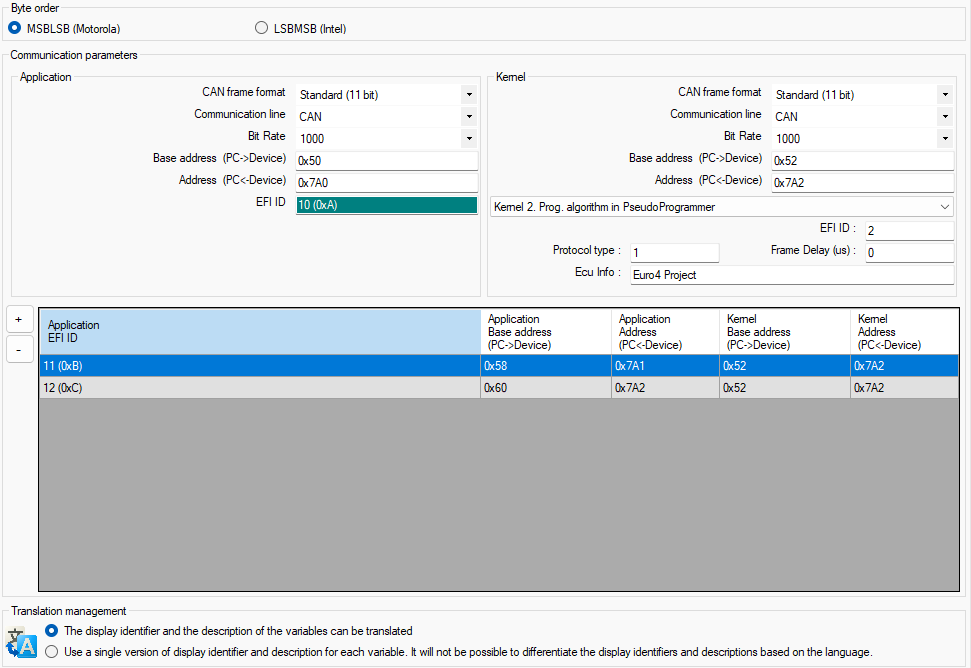


BYTE ORDER

There are two options that relate to the method of data representation in memory.

  • Motorola MSGLSB (in most EFI projects)
  • Intel LSBMSB

The option can only be changed if Expert mode is set

COMMUNICATION PARAMETERS

The communication parameters area is divided into 2 parts: application and kernel.

The application part contains the parameters for communicating with the application sw of the ECU. These parameters are used in monitoring the functioning of the unit and in the activities of calibration adjustment.

In this section you can manage

  • The CAN frame format (11 bit or 29 bit). Meaningful for CAN line only.
  • The type of communication line (CAN or K)
  • The bit rate (possible values 125,250,500,1000 for CAN line and 9600,19200,38400,57600 for K line)
  • The CAN ID for ECT requests to application sw of the ECU
  • The CAN ID for replies of application sw of the ECU to ECT.

In the case of the CAN line, is also shown the EFI ID that in fact is the requests ID / 8.

The EFI ID is used in some parts of ECT (log files, windows, information, etc.)

The kernel part contains the parameters for communicating with the ECU kernel sw. These parameters are used in programming the application sw and in some devices the calibrations.

In this section you can manage

  • The CAN frame format (11 bit or 29 bit). Meaningful for CAN line only.
  • The type of communication line (CAN or K)
  • The bit rate (possible values 125,250,500,1000 for CAN line and 9600,19200,38400,57600 for K line)
  • The CAN ID for ECT requests to kernel sw of the ECU
  • The CAN ID for replies of kernel sw of the ECU to ECT
  • The choice between legacy kernel and latest generation kernel

In the case in which the selected kernel is the latest generation kernel, there are also other parameters

  • EFI ID
  • Protocol type (usually 1)
  • Frame delay (usually 0)
  • ECU Info – different for each project and assigned by the EFI designers
The communication parameters can only be changed if Expert mode is set
LIST OF VIRTUAL DEVICES
If the special feature ‘List of IDs to create multiple virtual devices’ has been activated, the list of virtual devices is presented in the area below the area for defining communication IDs. These are devices that all refer to the same database but with different communication IDs. Virtual devices can help simplify the configuration of substantially identical devices that differ only in their ID. When managing devices with their own databases, it would be necessary to always keep the changes synchronized, while when managing them as virtual variants of a single device, they are always aligned. When using the device, the choice between the virtual variants of the device will be presented to direct the communication to one of the IDs in the list.

Was this helpful?

Yes  No
Related Articles
  • VERSION HISTORY
  • STRING FORMAT
  • APPENDICES
  • ASAP3
  • PRINT THE VALUES OF THE CALIBRATION VARIABLES
  • LINK ANALYSIS DISPLAY WITH ENGINE MAP

Didn't find your answer? Contact Us

Previously
TOP BAR MENU
Up Next
SCALINGS SECTION
Copyright 2026 EFI Technology S.r.l. (Company subject to the management and coordination activities of MTA S.p.A.) All Rights Reserved.
We use cookies to make sure you can have the best experience on our site. If you continue to use this site we will assume that you approve our use of cookies.